Answer:
Option B
Explanation:
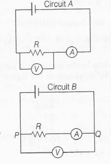
In the given circuits, A represents an ammeter, which is used to measured the current passing through the resistor it is not a low resistive device, so that it does not affect the circuit. It is connected in series with resistor.
Similarly, V represents a voltmeter , which is used to measure the potential drop across the resistor. It is usually a high resistive device, so that the negligible current passes through it . Thus , does not affect any current passing through the resistor.It is connected in parallel with to the resistor, This implies that, these devices are used measure. Current and voltage drop across a resistor , without actually affecting any of these quantities because of their addition in the circuit.
So, the given circuits A and B as shown below,

We can conclude that the circuit A has been correctly connected. Therefore , it can be used to measure R accurately , which can be calculated with the help of ammeter and voltmeter reading as ,
R= $\frac{ voltage (V)}{ current (I)}$ [ from ohm's law]
However, when the arrangement of ammeter and voltmeter is as per given in circuit B. The circuit then is usually used for measuring higher resistance as compare to circuit A.